In this article, the limited slip differential explained with video animation. Consider a situation, where a vehicle fitted with the standard differential move straight and one drive wheel is on a surface with excellent traction. The other wheel is on a slippery track. In a standard differential, the left and right axle rotations are entirely independent. Since one wheel is on a slippery track, the standard differential makes the wheel spin in excessive speed. While the excellent traction wheel remains almost dead. Which means high power supply to the slippery wheel and low power flow to the excellent traction wheel. So the vehicle won’t be able to move.
One way to overcome this problem is to limit the relative motion between the left and right axles. This is the reason to introduce limited slip differential. One of the most commonly used limited slip differential technology is clutch pack based.
Constructional features of limited slip differential
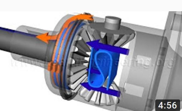
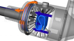
First, let’s go through it constructional features. Apart from its essential components, a limited slip differential has got a series of friction and steel plates packed between the side gear and the casing. Friction discs locked with the side gear. So the friction discs and the side gear always move together. Steel plates have external pads. It can fit in the case groove. So that they can rotate with the case. When activating a clutch pack assembly. The frictional force within them makes it move as a single solid unit. Since the steel plates locked with the case. The friction discs with the side gear, in a well-pressed clutch pack. Motion from the casing is directly passed to the corresponding axle.
Space between the side gears fitted with a pre-load spring. The pre-load spring always give a thrust force. This will press the clutch pack together.
You can note that spider and side gear are bevel gears. It has got one specialty. When torque is transmitted through a bevel gear system, axial forces are also induced apart from the tangential force. The axial force tries to separate out the gears. You can note that side gear and axle are two separate units. The side gear has got a small allowance for axial movement. So during high torque transmission through spider-side gear arrangement. A high separating thrust force is also transmitted to the clutch pack. This force presses and locks the clutch pack assembly against the casing.
Now, back to the initial problem.
Since one wheel is on a high traction surface, the torque transmitted to it will be higher. So the thrust force developed due to the bevel gear separation action also will be high at that side. The clutch pack get locked when the clutch pack at high traction wheel side presses firmly. So power from the differential casing flows directly to the high traction axle, via the clutch pack assembly. On the other hand, clutch pack on the low traction wheel side not engaged yet. So power flow be limited to that side. So the vehicle is able to overcome the traction difference problem.
However, while taking a turn, the limited slip differential can act as a standard differential. In this case thrust force developed due to the bevel gear separation action won’t be that high, so the plates in the clutch pack quickly overcome the frictional resistance and able to slip against each other. Thus the right and left wheel can have different speed, just like an open differential.
Drive wheel traction difference problem can be over come by there technologies.
1. Clutch type
2. Cone deferential
3. Hydraulic locking type
4. Torsen
We hope you like this article on limited slip differential. If you have any doubts, please feel free to post it in the comment section below.

Add comment